Jeffrey Gueble
Automation - Robotics - Mechatronics
Consulting & Custom Automation Development
Motor Assembly
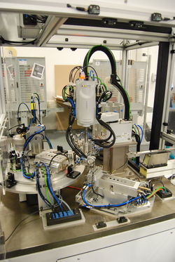
 Motor Assembly CellRear view of work cell at installation. |  MotorMotor in assembly nest. |
|---|---|
 Shaft InstallerPneumatic press for installing motor shafts. |  Magnet FeederRare earth magnet feeder. |
 Shaft NestPick nest for motor shaft. |  GripperMulti-gripper over shaft installer. |
 Rear ViewView of magnet feeder from rear of work cell. |  Robot I/OEtherCAT robot I/O pack mounted to back of robot arm. |
 Side ViewSide view of cell showing shaft installer and shaft gauging station. |  Front ViewFront view of work cell showing operator area and light curtain. |
 Front ViewFront view of work cell showing bowl feeder in the rear. |  Side ViewSide view of work station showing magnet feeder, and vision station. |
The lean motor assembly cell is built around a small indexing table. The operator, sitting at the front of the machine, loads the motor assembly into the assembly nest.
At the first station, a pneumatic mechanism applys two dots of adhesive to the motor. At the next station, the adhesive is inspected with machine vision to verify that sufficient adhesive is present.
At the next station, the robot acquires two magnets from a dual-lane feeder, which are placed onto the adhesive dots on the motor.
After magnet installation, the motor shaft is fed from a bowl, and then placed into a pneumatic press, which inserts the shaft into a boss on the motor.
Finally, the shaft extension is verified with simple optical sensors, and the operator removes it from the indexer nest. A simple light system indicates that the shaft insertion was successful.